| ย้อนกลับ | กลับสู่เมนูหลัก |
Appendix 5 AntiPass Back ★
【overview】
Sometimes, some illegal people follow the other one into the gate, which will cause the security problems. To prevent such risks, this function is enabled. The In record must match the Out record, or the gate won’t open.
This function needs two machines to work together. One is installed inside of the door (master machine hereinafter), the other is installed outside of the door (slave machine hereinafter). Wiegand signal communication is adopted between the two machines.
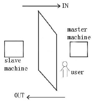 【Working principle】
The master machine has Wiegand In and slave machine has Wiegand Out functions. Connect Wigand Out of slave machine to Wiegand In of master machine. Wiegand output from slave machine must not own machine ID. The number sent to master machine from slave machine must be found in the master machine.
【Function】
Judge whether it is antipass back according to user’s recent inout record. In record and out record must be matched. This machine supports out, in, or outin antipass back.
When the master machine is set as “out antipass back”, if user wants to come in and go out normally, his recent record must be “in”, or he cannot go out. Any “out” attempt will be refused by “antipass back” function. For example, a user’s recent record is “in”, his second record can be “out” or “in”. His third record is based on his second record. Out record and in record must match.(Notice: If customer has no record before, then he can come in but cannot go out. )
When the master machine is set as “in antipass back”, if the user wants to come in and go out normally, his recent record must be “out”, or he cannot go out. Any out record will be “antipass back refused” by the system. (Notice: If the customer has no former record, then he can go out, but cannot come in).
When the master machine is set as “outin antipass back”, if the user wants to come in and go out normally, if his recent record is “out” and “in”, then his next record must be “in” and “out”.
【operation】
1. Select model
Master machine: The machine with Wiegand in function, except for F10 reader.
Master machine: The machine with Wiegand in function, except for F10 reader.
2. Menu setting
Antipass back
There are four options: in/out antipass back, out antipass back, in antipass back, and none.
Out antipass back: Only user’s last record is inrecord, can the door be open.
In antipass back: Only user’s last record is outrecord, can the door be open.
Device status: There are three options: Controlin, controlout and none
Controlin: When it is set, the verified records on the device are inrecords.
Controlout: When it is set, the verified records on the device are outrecords.
None: When it is set, close the device’s antipass back function.
3. Modify device’s Wiegand output format
When the two devices are communicating, only the Wiegand signals without device ID are received. Enter device menu-> communication option-> Wiegand option or enter software > basic setting > device management > Wiegand, to modify “defined format” as “wiegand26 without device ID”.
4. Enroll user
The user must be on master machine and slave machine at the same time, and user PIN must be the same. Therefore, it is necessary to enroll user on master machine and slave machine at the same time.
5. Connection instruction
Wiegand communication is adopted for master machine and slave machine. Refer to the following for connection: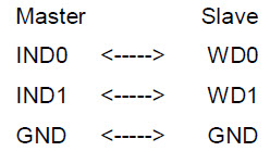
| ย้อนกลับ | กลับสู่เมนูหลัก | ถัดไป |
Besides this function only is owned by the fingerprint access control machine that has been appointed, most of the fingerprint machines only have two ways to verify by fingerprint and password, we provide a personal or group Multicombination Authentication Mode for high security Access control area, verification type main include five elements that are User Number (PIN), Fingerprint (FP), Face (FACE), Password (PW) and RF card (RF), which can combine into multicombination.
![]() Note: The RF card is used for ID card verification, the function of ID card verification only is validity in the machine which ID card function is provided with.
Note: The RF card is used for ID card verification, the function of ID card verification only is validity in the machine which ID card function is provided with.
These symbols illustrate what follow the table different means.
If Fingerprint, Face, Password and Card have been enrolled for the user, the verification procedure is follow.
![]() Note: For combined verification, it is better to enroll all the elements in need for using verification mode, or verification will fail.
Note: For combined verification, it is better to enroll all the elements in need for using verification mode, or verification will fail.
For example: User “A” use fingerprint for enrollment, while password is used for verification, then the user cannot pass the verification.
| ย้อนกลับ | กลับสู่เมนูหลัก | ถัดไป |
Appendix 3 Photo ID Function
The Photo ID function is used to display the photo enrolled by a user or stored in a USB disk on the screen in addition to such information as the user ID and name.
[Operation Steps]
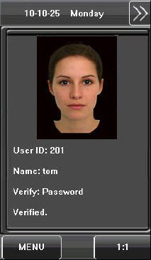 1. When the photo taken by the device is used, the photo can be displayed upon successful verification.
2. To use a photo stored in a USB disk, proceed as follows:
1) Create a folder with the name of “photo” in the USB disk, and store users’ photos under this folder.
2) The user photos must be in JPG format and named after their IDs. For example, for the user with the user ID of 154, the photo name must be 154.jpg.
3) Insert the USB disk into USB slot on the device, and select USB Disk Management > Upload > Upload Photos. Then user photos can be displayed upon successful verification.
![]() Note:
Note:
1) The length of a user name cannot exceed 24 digits.
2) The recommended size of a user photo is less than 30 kbit.
3) The uploaded new user photo will overwrite the existing photo in related to the user ID.
4) To download user photos, select USB Disk Management > Download > Download User Photos. A folder with the name of “photo” will be automatically created on the USB disk, and all downloaded user photos are stored under this folder.
| ย้อนกลับ | กลับสู่เมนูหลัก | ถัดไป |
Wiegand26 is an access control standard protocol established by the Access Control Standard Subcommittee affiliated to the Security Industry Association (SIA). It is a noncontact IC card reader interface and output protocol. Wiegand26 defines the interface between the card reader and controller used in the access control, security and other related industrial fields. Wiegand26 helps standardize the work of the card reader designers and controller manufacturers. The access control products manufactured by our company are also designed by following this protocol.
Digital Signals
The figure below is a sequence diagram in which the card reader sends digital signals in bit format to the access controller. In this sequence diagram, Wiegand follows the SIA’s access control standard protocol for the 26bit Wiegand card reader (one pulse time ranges between 20 us and 100 us, and the pulse jump time ranges between 200us and 20ms). Data1 and Data0 are high level (larger than Vol) signals till the card reader prepares to send a data stream. The asynchronous lowlevel pulse (smaller than Vol) generated by the card reader is sent to the access control panel (The sawtooth wave as shown in Figure below) through Data1 or Data0. Data1 and Data0 pulses will neither overlap nor be generated synchronously. The table below lists the maximum and minimum pulse width (a consecutive pulse) and pulse jump time (time between pulses) allowed by the F series fingerprint access control device.
Figure: Sequence Diagram
Table: Pulse Time
| ย้อนกลับ | กลับสู่เมนูหลัก | ถัดไป |
Appendix 1 T9 Input Instructions
The device supports to input English characters, numbers and symbols. Press related button to input text. For example, press [Name] to display the text input interface, as shown in the figure:
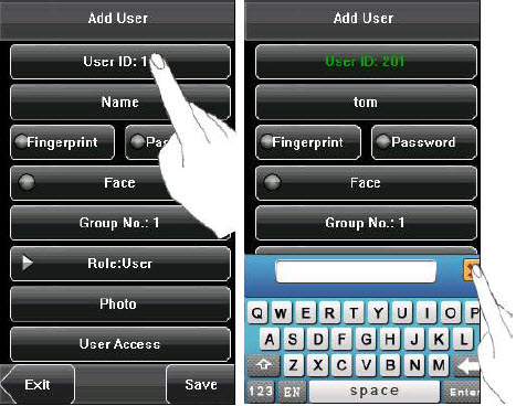
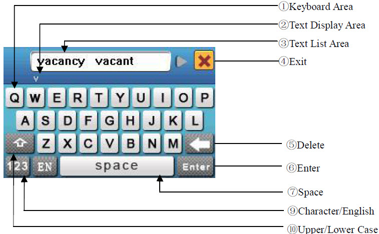 To enter a name, proceed as follows:
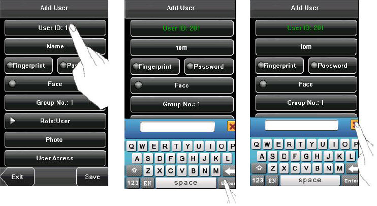
1. Press [Name] on the [Add] interface, as shown in figure below.
2. Enter the letter characters, and a list of characters in relation to the letter is presented in the text display area.
3. If the desired character is displayed in the text display area, press this character. And this character is at the same time displayed on the [Name] button. Enter next character by repeating Step 2.
4. After finishing the entry of name, press [X] to exit the keyboard interface and return to the previous interface.
| ย้อนกลับ | กลับสู่เมนูหลัก | ถัดไป |
Through the [Dn/Upload] menu, you can download user information and attendance data stored in a USB disk to related software or other fingerprint recognition equipment.
1. Download Transactions: Download all the attendance data from the device to a USB disk.
2. Download User: Download all the user information, fingerprints and face images from the device to a USB disk.
3. Download user photos: Download the employees’ photos from the device to a USB disk.
4. Upload User: Upload the user information, fingerprints and face images stored in a USB disk to the device.
5. Upload User Photo: Upload the JPG documents that are named after the user IDs and stored in a USB disk to the device, so that user photos can be displayed after the employee passes the verification. See Appendix 3 Photo ID Function.
| ย้อนกลับ | กลับสู่เมนูหลัก | ถัดไป |
9. Auto Test
The auto test enables the system to automatically test whether functions of various modules are normal, including the screen, sensor, voice, face, keyboard and clock tests.
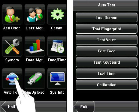 1. Test Screen: The device automatically tests the display effect of the color TFT display by displaying full color, pure white and pure black and checks whether the screen displays properly. You can continue the test by touching the screen or exit it by pressing [Exit].
2. Test Fingerprint: The device automatically tests whether the fingerprint sensor works properly by checking whether the fingerprint images are clear and acceptable. When the user places his/her finger on the sensor, the collected fingerprint image is displayed on the screen in realtime. Press [Exit] to exit the test.
3. Test Voice: The device automatically tests whether the voice files are complete and the voice quality is good by playing the voice files stored in the device. You can continue the test by touching the screen or exit it by pressing [Exit].
4. Test Face: The device automatically tests whether the camera works properly by checking whether the collected face images are clear and acceptable. Press [Exit] to exit the test.
5. Test Keyboard: The device tests whether every key on the keyboard works normally. Press any key on the [Keyboard Test] interface to check whether the pressed key matches the key displayed on screen. The keys are darkgray before pressed, and turn blue after pressed. Press [Exit] to exit the test.
6. Test Time: The device tests whether its clock works properly by checking the stopwatch of the clock. Touch the screen to start counting, and touch it again to stop to check whether the counting is accurate. Press [Exit] to exit the test.
7. Screen Calibration: You can perform all the menu operations by touching the screen with one of your fingers or a touch pen. When the touch screen is less sensitive to the touch, you can perform a screen calibration through menu operations.
The Screen Calibration Operation:
 (1) Press [Menu] on the initial interface to display the main menu interface.
(2) Press [Calibration] on the [Auto Test] interface to display the screen calibration interface.
(3) Touch the center of the cross “+”.
(4) Repeat Step 3 following the move of the “+” icon to different locations on the screen.
(5) Touch the center of the cross at five locations on the screen correctly. When the message “Calibrating screen, pls wait……” is displayed on screen, the calibration succeeds and the system automatically returns to the main menu. If the calibration fails, the system recalibration will start from Step 3.
| ย้อนกลับ | กลับสู่เมนูหลัก | ถัดไป |
Lots of companies need to ring their bells to signal the start and end of work shifts, and they usually manually ring their bells or use electric bells. To lower costs and facilitate management, we integrated the time bell function into the device. You can set the alarm time and duration for ringing the bell based on your requirements, so that the device will automatically play the selected ring tone and triggers the relay at the alarm time, and stop playing the ring tone after the set duration. Press [Bell] on the [Date/Time] menu to display the bell setting interface, as shown in figure below.
1. Add a bell 1) The displayed bell setting interface lists all the bells. Click [Add] to display the [Add] interface. 2) On the [Add] interface, set the following parameters: Bell Time: This parameter is used to set a time point when the device automatically plays a bell ring tone every day. Bell Date: This parameter is used to set which day the device automatically plays a bell ring tone.
Ring Tone: This parameter is used to set the bell ring tone.
Volume: This parameter is used to set the volume of ring tone.
Repeat: This parameter is used to set the alarm times.
State: This parameter is used to set whether to enable the bell.
Bell Type: You can select between internal ringing and external ringing. For internal ringing, the ring tone is played by the loudspeaker of the device. For external ringing, the ring tone is played by an external electric bell that is connected with the device.
2. Edit and delete a bell
Press a bell in the list on the bell setting interface to display the [Edit] interface, with the similar operation as “Add a bell”.
![]() Notice: Only some models have this function. If you need it, please contact our business representative or technician.
Notice: Only some models have this function. If you need it, please contact our business representative or technician.
| ย้อนกลับ | กลับสู่เมนูหลัก | ถัดไป |
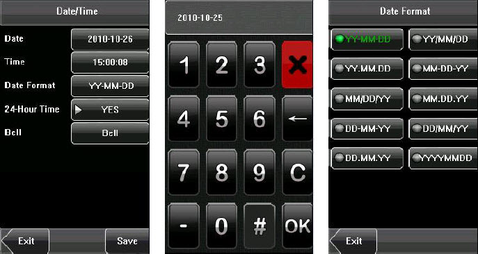
8.1 Set Date/Time
The date and time of the device must be set accurately to ensure the accuracy of attendance time.
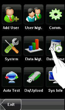 1. Press [Menu] on the initial interface to display the main menu interface.
2. Press [Time/Date] on the main menu interface to display the time setting interface.
3. Select the desired date and time by pressing the parameter. For the time format, there are 10 formats to select from. Both 12hour and 24hour time systems are supported.
4. Press [Save] to save the current information and return to the previous interface. Press [Exit] to return to the previous interface without saving the current information.
| ย้อนกลับ | กลับสู่เมนูหลัก | ถัดไป |
Copyright © 2014 · All Rights Reserved · ICT Smart Co., Ltd.
No part of this website or any of its contents may be reproduced, copied, modified or adapted, without the prior written consent of the author, unless otherwise indicated for stand-alone materials. You may share this website by any of the following means: 1. Using any of the share icons at the bottom of each page (Google Mail, Blogger, Twitter, Facebook, Google+); 2. Providing a back-link or the URL of the content you wish to disseminate; and 3. You may quote extracts from the website with attribution to www.ictsmart.com